How to use the Pro Mini XL or Atmega 1284p with the Arduino IDE
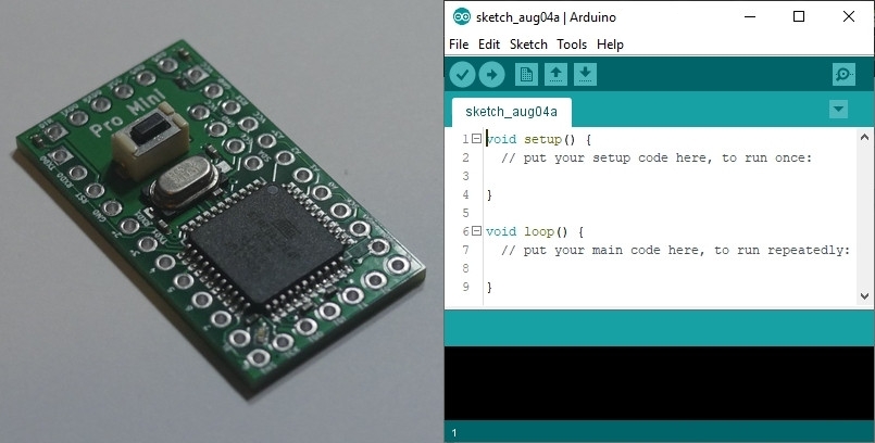
Adding a New Board Library
Following the steps below will enable the Arduino IDE to compile and upload code to an Atmega 1284p chip or one of the Pro Mini XL (v1, v2 or USB) boards.
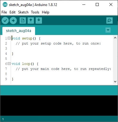
Step 1: Launch the Arduino IDE.
I’m using version 1.8.12 or above in the screenshots that follow.
Step 2: Navigate to File ⇨ Preferences
Tip: Or just press Ctrl+Comma.
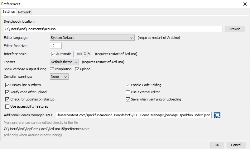
The following window should appear…
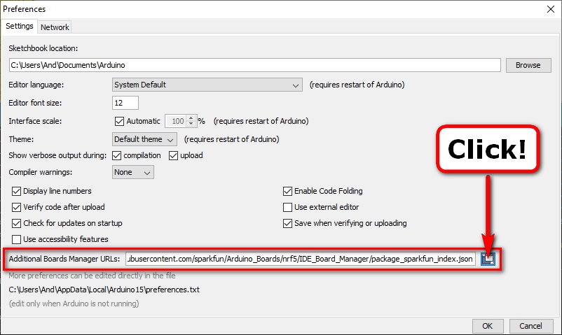
Step 3: Open the Additional Boards Manager URLs window.
The following new window should appear…
Note: The textbox in your window may already contain URLs to additional board packages – one on each line.
Step 4: Add the following URL on a new line in the above text box:
https://mcudude.github.io/MightyCore/package_MCUdude_MightyCore_index.json
Step 5: Close and relaunch the Arduino IDE.
Note: Any change to the Additional Boards Manager URLs requires a relaunch for those changes to take effect.
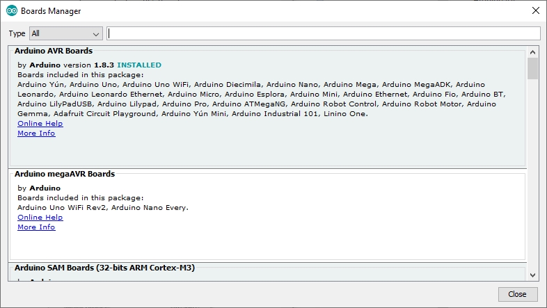
Step 6: Navigate to Tools ⇨ Board: ⇨ Board Manager…
The following window should appear, but note that the available versions may well be different…
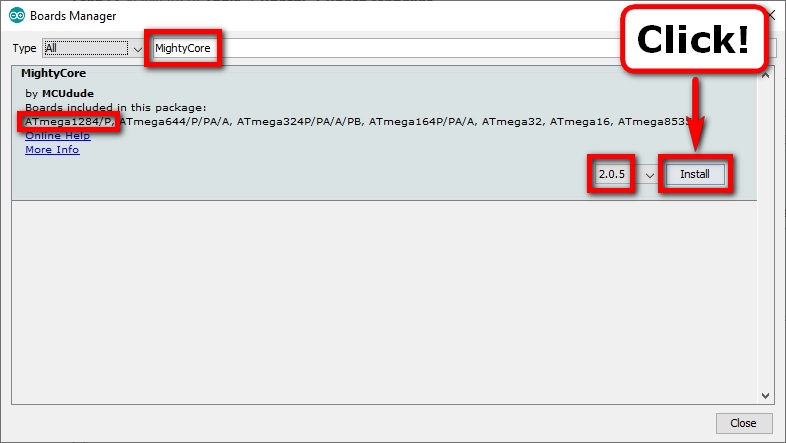
Step 7: Search for and install the latest version of the following Board Support Package…
MightyCore
All Pro Mini XL boards (v1, v2 and USB) have been tested with the latest version (v2.1.8 as of September 2022).
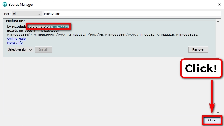
However I’m using version 2.0.5 in the screenshot below:
Step 8: After the Board Support Package has finished installing, close the Board Manager window.
You should now be able to configure your new board.
Configuring Your New Board
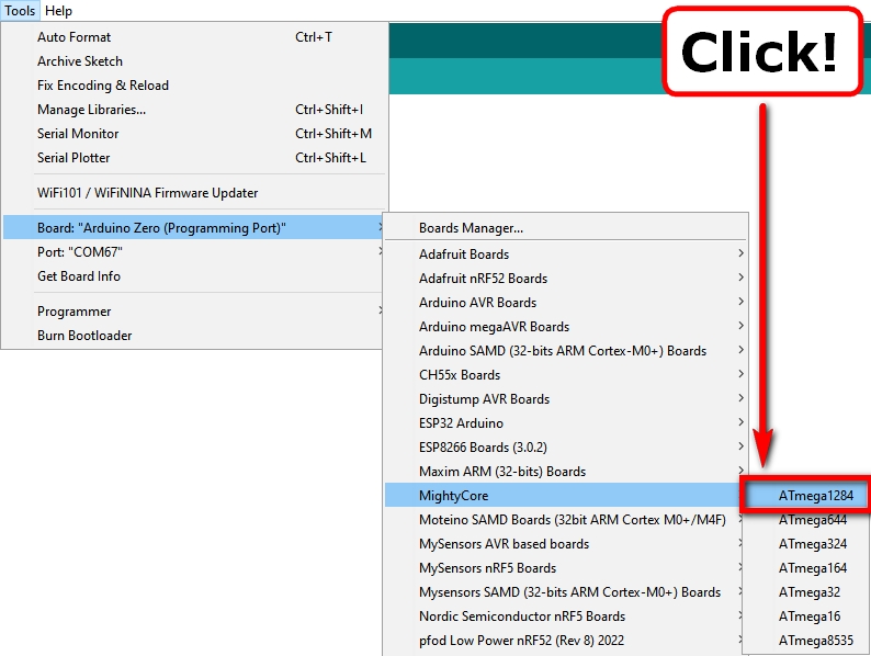
Step 1: Navigate to Tools ⇨ Board: ⇨ MightyCore (Section) and select the following:
Atmega1284
Note: This will update the board configuration options to those for the selected board.
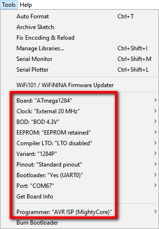
Step 2: Navigate to the Tools menu and select the following options for the Pro Mini XL:
Note: If you are using a different Atmega1284-based board, select the options that best match your board.
Clock: "External 20 MHz"
BOD: "BOD 4.3V"
EEPROM: "EEPROM retained"
Compiler LTO: "LTO Disabled"
Variant: "1284P"
Pinout: "Standard pinout"
Bootloader: "Yes (UART0)"
Port: "[Your COM Port Here!]

Programmer: "[Your ISP/ICSP Programmer Here!]"  (If you are using one...)
Note: For more information about the available options, please visit the Github repository for MightyCore.
You should now be able to compile and upload code to your board.
Enjoy!
Optional: Creating a Custom Board and Options for the Pro Mini XL Series
Following the steps below will add some new custom board pinouts for the Pro Mini XL board series (v1, v2 and USB) and associated options to the Boards menu.
This enables you to:
- Easily switch between the different pinout versions (v1 and v2) of the Pro Mini XL
- Burn different bootloaders to clock your XL at different frequencies (8 MHz and 1MHz) to save power.
- If you have the v2 USB version, use the built-in ISP/ICSP programmer to burn different bootloaders from within the Arduino IDE.
Step 1: Navigate to File ⇨ Preferences
Tip: Or just press Ctrl+Comma.
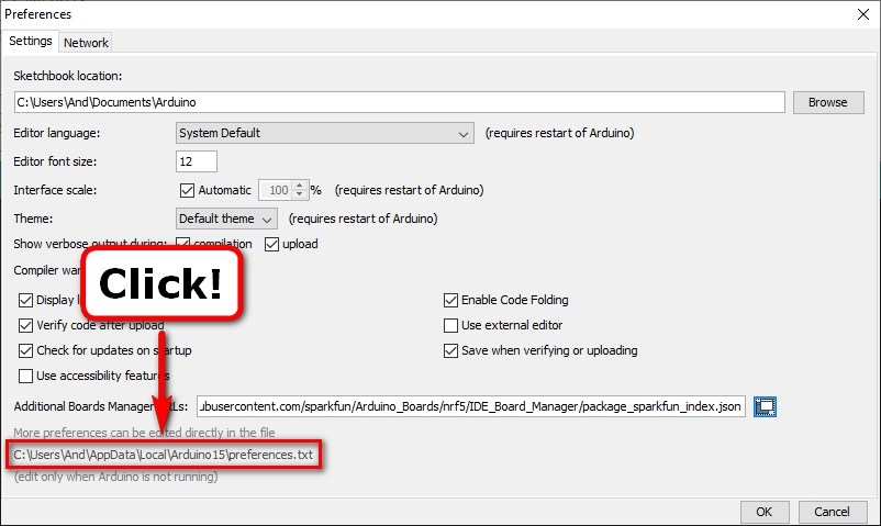
The following window should appear…
Step 2: Click on the direct link to the Arduino IDE preferences file as shown below:
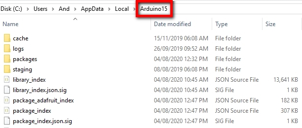
A new window should open showing the contents of the [Your-User-Area-Here]\Arduino15 directory:
Step 3: Navigate to the following directory:
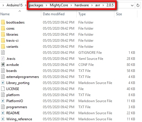
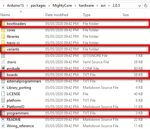
packages\MightyCore\hardware\avr\<version>
Note: It should look something like this for version 2.0.5; later versions should be very similar:
Step 4: Download and extract the ZIP archive from this Github repository into the above directory.
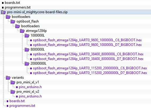
The ZIP archive contains the following files and internal structure:
Extracting should overwrite the existing boards.txt and programmers.txt files.
It will also add Pro Mini XL specific directories and associated files into the variants and bootloaders directories.
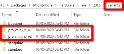
You should now see two new directories in the variants directory:
You should also now see more bootloaders available in the bootloader directories.
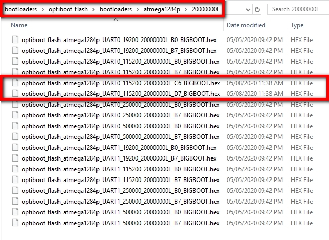
For example, in:
bootloaders\optiboot_flash\bootloaders\atmega1284p\20000000L
You should see the following two new bootloaders available:
Additional bootloaders are added in the following two other directories:
bootloaders\optiboot_flash\bootloaders\atmega1284p\8000000L
bootloaders\optiboot_flash\bootloaders\atmega1284p\1000000L
Step 5: Close and relaunch the Arduino IDE.
Step 6: Navigate to Tools ⇨ Board: ⇨ MightyCore (Section) and select the following:
ATmega1284
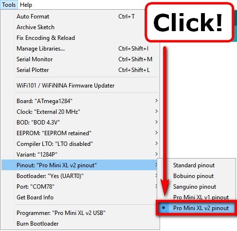
Step 7: Navigate to the Tools menu and select the following options:
Clock: "External 20 MHz"
BOD: "BOD 4.3V"
EEPROM: "EEPROM retained"
Compiler LTO: "LTO disabled"
Variant: "1284P"
Pinout: "Pro Mini XL v2 pinout"  [Or v1, if you have a v1 board.]
Bootloader: "Yes (UART0)"
Step 8: If you have the USB version of the Pro Mini XL v2, the board should provide you with two COM ports when you plug it in:
COM Port A:  Connects to UART0 on the ATmega1284p for Uploading and Serial Debugging
COM Port B:  Connects to SPI I/F on the ATmega1284p for ISP/ICSP Programming and Bootloader Burning
Note: The COM port numbers will vary depending on how your PC enumerates the ports and in what order.
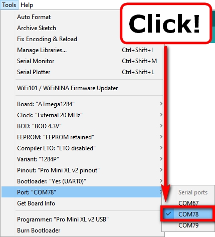
Therefore, if you want to upload compiled code to your Pro Mini XL v2 USB, then select the COM port that connects to UART0 on the ATmega1284p:
Port: "COM Port of UART0 on ATmega1284p" [This is usually the first new COM port created.]
Note: In my case below, this is COM78.
You should now be able to compile and upload code to your board.
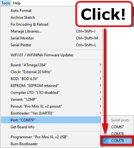
Or if you want to burn a new bootloader to your Pro Mini XL v2 USB, then select the COM port that connects to the SPI Interface on the ATmega1284p:
Port: "COM Port of SPI I/F on ATmega1284p" [This is usually the second new COM port created.]
Note: In my case below, this is COM79.
Pre-compiled bootloaders are available in the Arduino Board Files downloaded above for clocking the Pro Mini XL v2 USB from an Internal 8 or 1 MHz clocks.
Clock: "Internal 8 MHz" or "Internal 1 MHz"
Note: You may also want to update the BOD and EEPROM fuse settings too. For 8 MHz a BOD of 2.7v is recommended, for 1 MHz a BOD of 1.8v is recommended.
You should now be able to burn a new bootloader to your board.


0 Comments