How to make an AVR Programmer out of a Pro Mini – Part 2: HVSP/HVPP
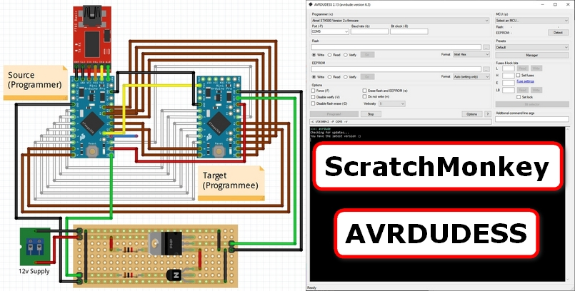
Please follow the steps outlined in Part 1 to create an ISP/ICSP/HVSP/HVPP/TDI programmer out of an existing 5v 16MHz Pro Mini.
It uses a slightly modified version of the excellent ScratchMonkey code by Matthias Neeracher – much thanks and appreciation should be directed his way!
This new programmer can then be used to change fuses, flash bootloaders and even potentially resurrect “bricked” AVR chips – even on Pro Minis!
Part 1 of this series uploads the code and tests the ISP/ICSP functionality.
It also includes a useful feature that might enable the resurrection of “bricked” AVR chips/Pro Minis whose CKSEL fuse bits have been incorrectly set.
Part 2 (this part) of this series details building some extra circuitry to utilize the HVSP/HVPP functionality.
This enables the programmer to resurrect a “bricked” AVR chip/Pro Mini whose RSTDISBL, DWEN and/or SPIEN fuse bits have been incorrectly set.
Building a High Voltage Switch
The HVSP/HVPP functionality of the Pro Mini-based Programmer requires building some external circuitry to switch a +12v signal to the target’s nRESET pin.
There are many ways to do this; the one shown below was simply the method chosen for this example.
For more examples, please see the Bald Engineer’s awesome article on transistor switches.
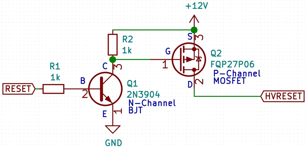
Step 1: Familiarize yourself with the circuit schematic shown below:
The above circuit schematic shows a simple high voltage (+12v) switch from a low voltage source (+5v microcontroller like the Pro Mini).
Applying a +5v signal to the RESET input will generate a +12v signal at the HVRESET output for as long as the +5v signal is applied.
This will enable the Pro Mini-based Programmer created to generate the necessary +12v signal to the target microcontroller’s nRESET pin.
Step 2: Assemble the necessary components:
| Part | Description | Datasheet | OctoPart |
|---|---|---|---|
| R1, R2 | 1k Ohms, 1/8 Watt, Metal Film | N/A | N/A |
| Q1 | 2N3904 N-Channel BJT | via SparkFun | Link |
| Q2 | FQP27P06 P-Channel MOSFET | via SparkFun | Link |
Step 3: Build the above high voltage switch circuit.
This can be done on a breadboard, perfboard or stripboard.
You may also require a +12v power supply. This could be either a mains standalone type or a variable buck or boost module type.
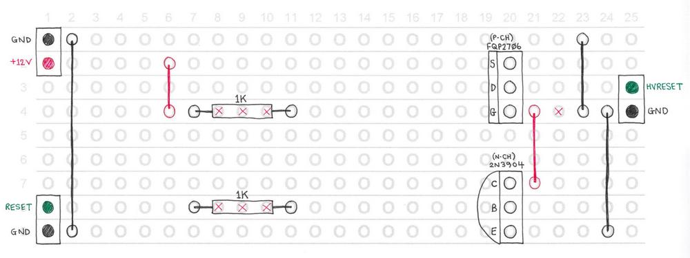
An example layout using stripboard has been shown below:
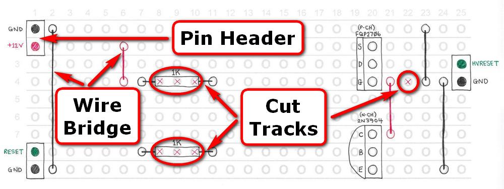
Note: The layout below also uses 3x 2-pin 2.54mm male headers, 5x wire bridges. A stripboard track cutter or large-sized drill bit can be used to cut the tracks.
Step 4: Test the high voltage switch circuit.
For example, by:
- Connecting a +12v power supply between the +12v pin and GND at the top-left in the above layout.
- Then touching a +5v signal between the RESET pin and GND at the bottom-left in the above layout.
- And measuring the voltage between the HVRESET pin and GND on the right in the above layout.
The HVRESET pin should measure approx. +12v whenever a +5v signal is applied to the RESET pin.
Assuming the measurements are correct, the programmer and high voltage switch circuit can now be connected to the target to be programmed.
Congratulations! You have finished building the high voltage switch.
Connecting the Programmer via HVPP
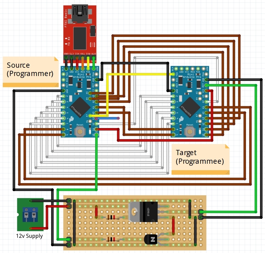
Step 1: Connect the Pro Mini-based Programmer and High Voltage Switch to the target board you want to program using the following HVPP connections:
Note: There are more detailed connection descriptions as you scroll down this page.
The following table details the exact connections from pin numbers on a Source (Programmer) Pro Mini-based to the Target (Programmee) Pro Mini:
|
Source (Programmer) Board Pin |
Target (Programmee) Board Pin |
Connection Color |
| 12 | A2 | White |
| 2 | 2 | White |
| 3 | 3 | White |
| 4 | 4 | White |
| 5 | 5 | White |
| 6 | 6 | White |
| 7 | 7 | White |
| A0 | 8 | Brown |
| A1 | 9 | Brown |
| A2 | 10 | Brown |
| A3 | 11 | Brown |
| A4 | 12 | Brown |
| A5 | 13 | Brown |
| 8 | A0 | Brown |
| 9 | A1 | Brown |
| 11 | VCC | Red |
| GND | GND | Black |
| A7 | TXD | Yellow |
| 13 |
XTAL1 [On AVR Chip] |
Blue |
| 10 |
RESET [On High Voltage Switch] |
Green |
| GND |
GND [On High Voltage Switch] |
Black |
|
HVRESET [On High Voltage Switch] |
RST | Green |
|
GND [On High Voltage Switch] |
GND | Black |
If you would like more detail regarding the connections please see the table below:
| Source (Programmer) | HVPP Signal | Connection Color | Target (Programmee) | ||||
| Board Pin | Chip Pin | Function | Board Pin | Chip Pin | Function | ||
| 12 | 16 | PB4 / MISO | CTRL0 / BS2 | White | A2 | 25 | PC2 / ADC2 |
| 2 | 32 | PD2 / INT0 | CTRL2 / OE | White | 2 | 32 | PD2 / INT0 |
| 3 | 1 | PD3 / INT1 / OC2B | CTRL3 / WR | White | 3 | 1 | PD3 / INT1 / OC2B |
| 4 | 2 | PD4 / T0 / XCK | CTRL4 / BS1 | White | 4 | 2 | PD4 / T0 / XCK |
| 5 | 3 | PD5 / T1 / OC0B | CTRL5 / XA0 | White | 5 | 3 | PD5 / T1 / OC0B |
| 6 | 4 | PD6 / AIN0 / OC0A | CTRL6 / XA1 | White | 6 | 4 | PD6 / AIN0 / OC0A |
| 7 | 5 | PD7 / AIN1 | CTRL7 / PAGEL | White | 7 | 5 | PD7 / AIN1 |
| A0 | 23 | PC0 / ADC0 | DATA[0] | Brown | 8 | 12 | PB0 / CLK0 / ICP1 |
| A1 | 24 | PC1 / ADC1 | DATA[1] | Brown | 9 | 13 | PB1 / OC1A |
| A2 | 25 | PC2 / ADC2 | DATA[2] | Brown | 10 | 14 | PB2 / MISO |
| A3 | 26 | PC3 / ADC3 | DATA[3] | Brown | 11 | 15 | PB3 / MOSI / OC2A |
| A4 | 27 | PC4 / ADC4 / SDA | DATA[4] | Brown | 12 | 16 | PB4 / MISO |
| A5 | 28 | PC5 / ADC5 / SCL | DATA[5] | Brown | 13 | 17 | PB5 / SCK |
| 8 | 12 | PB0 / CLK0 / ICP1 | DATA[6] | Brown | A0 | 23 | PC0 / ADC0 |
| 9 | 13 | PB1 / OC1A | DATA[7] | Brown | A1 | 24 | PC1 / ADC1 |
| 11 | 15 | PB3 / MOSI / OC2A | VCC | Red | VCC | VCC | VCC and AVCC |
| GND | GND | GND | GND | Black | GND | GND | GND |
| A7 | 22 | ADC7 | RDY / nBSY | Yellow | TXD | 31 | PD1 / TXD |
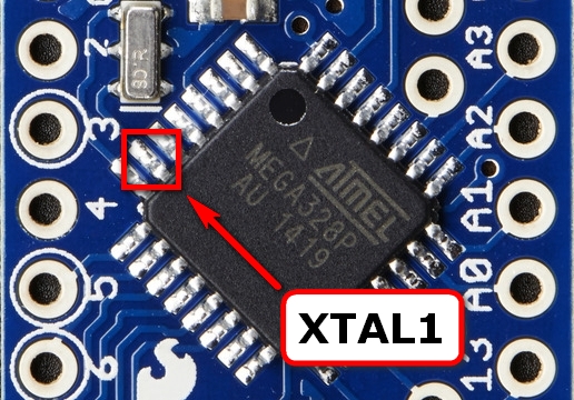
| 13 | 17 | PB5 / SCK | XTAL | Blue | N/A | 9 | PB6 / XTAL1 / TOSC1 |
| 10 | 14 | PB2 / SS / OC1B | RESET | Green | [On High Voltage Switch] | ||
| [On High Voltage Switch] | HVRESET | Green | RST | 29 | PC6 / RST | ||
The short, floating blue wire should connect from pin 13 on the programmer to the XTAL1 pin on your target board – for example, shown below on a ATmega328p chip on a Pro Mini.
Note: Try to make a secure/reliable connection, e.g. solder the wire – however you can sometimes get away with simply holding the wire to the microcontroller pin.
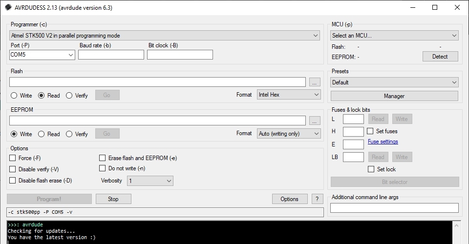
Select the following programmer protocol from the Programmer dropdown menu:
Atmel STK500 V2 in parallel programming mode
Select the COM port of the FTDI programmer attached to the Pro Mini-based programmer from the Port dropdown menu:
Note: In the screenshot below, the FTDI programmer has been enumerated to COM5 – your programmer will likely be different.
Step 3: Using AVRDUDE, attempt to detect the target microcontroller.
Assuming detection is successful, the microcontroller type will be displayed:
Note: If detection is unsuccessful, first double-check the connections between the Pro Mini Programmer and the target board.
Note: If using AVRDUDESS, the GUI will update the detected Microcontroller type:
Congratulations! You can now modify the microcontroller fuse bits, flash and EEPROM using HVPP.
Connecting the Programmer via HVSP
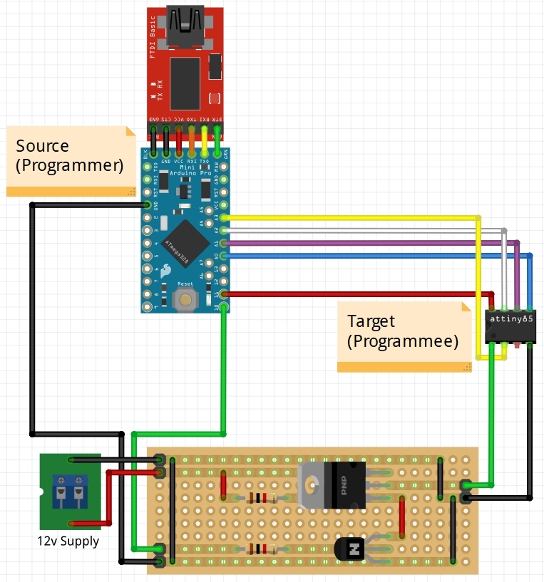
Step 1: Connect the Pro Mini-based Programmer and High Voltage Switch to the target board you want to program using the following HVSP connections:
Note: There are more detailed connection descriptions as you scroll down this page.
The following table details the exact connections from pin numbers on a Source (Programmer) Pro Mini-based to the Target (Programmee) Pro Mini:
|
Source (Programmer) Board Pin |
Target (Programmee) Board Pin |
Connection Color |
| A0 | 5 | Blue |
| A1 | 6 | Purple |
| A2 | 7 | White |
| A3 | 2 | Yellow |
| 11 | 8 | Red |
| 10 |
RESET [On High Voltage Switch] |
Green |
| GND |
GND [On High Voltage Switch] |
Black |
|
HVRESET [On High Voltage Switch] |
1 | Green |
|
GND [On High Voltage Switch] |
4 | Black |
If you would like more detail regarding the connections please see the table below:
| Source (Programmer) | HVSP Signal | Connection Color | Target (Programmee) | ||||
| Board Pin | Chip Pin | Function | Board Pin | Chip Pin | Function | ||
| A0 | 23 | PC0 / ADC0 | SDI | Blue | N/A | 5 | PB0 |
| A1 | 24 | PC1 / ADC1 | SII | Purple | N/A | 6 | PB1 |
| A2 | 25 | PC2 / ADC2 | SDO | White | N/A | 7 | PB2 |
| A3 | 26 | PC3 / ADC3 | SCI | Yellow | N/A | 2 | PB3 |
| 11 | 15 | PB3 / MOSI / OC2A | VCC | Red | N/A | 8 | VCC |
| GND | GND | GND | GND | Black | N/A | 4 | GND |
| 10 | 14 | PB2 / SS / OC1B | RESET | Green | [On High Voltage Switch] | ||
| [On High Voltage Switch] | HVRESET | Green | N/A | 1 | PB5 | ||
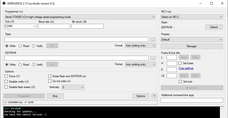
Select the following programmer protocol from the Programmer dropdown menu:
Atmel STK500 V2 in high-voltage serial programming mode
Select the COM port of the FTDI programmer attached to the Pro Mini-based programmer from the Port dropdown menu:
Note: In the screenshot below, the FTDI programmer has been enumerated to COM5 – your programmer will likely be different.
Step 3: Using AVRDUDE, attempt to detect the target microcontroller.
By default, AVRDUDESS does not include an HVSP control stack for the “Detect” command.
To add one, open the AVRDUDESS avrdude.conf file in your favorite code editor and add the following lines for the ATmega8 part:
hvsp_controlstack = 0x4C, 0x0C, 0x1C, 0x2C, 0x3C, 0x64, 0x74, 0x66,
                    0x68, 0x78, 0x68, 0x68, 0x7A, 0x6A, 0x68, 0x78,
                    0x78, 0x7D, 0x6D, 0x0C, 0x80, 0x40, 0x20, 0x10,
                    0x11, 0x08, 0x04, 0x02, 0x03, 0x08, 0x04, 0x00;
hvspcmdexedelay   = 0;
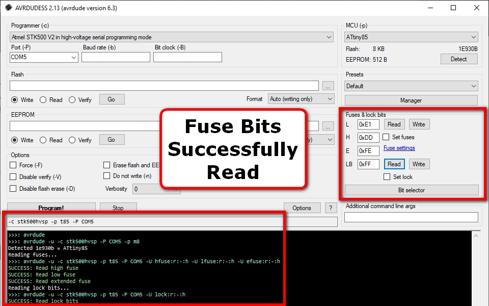
After editing, simply click the “Detect” button in the AVRDUDESS GUI:
Assuming detection is successful, the microcontroller type will be displayed:
Note: If detection is unsuccessful, first double-check the connections between the Pro Mini Programmer and the target board.
Note: If using AVRDUDESS, the GUI will update the detected Microcontroller type:
Congratulations! You can now modify the microcontroller fuse bits, flash and EEPROM using HVSP.
Example: Resurrecting a “bricked” Pro Mini using HVPP
Mistakes can sometimes be made when debugging microcontrollers.
One common mistake is accidentally removing the microcontroller before the debugger has reset the SPIEN/DWEN/RSTDISBL fuse bits.
This can result in the microcontroller becoming completely unresponsive to any ISP/ICSP programming (with or without an external clock).
Or responding with an unknown signature, e.g. 0x000102 as shown below:
Using high voltage programming (HVSP/HVPP) is the only way to resurrect such an apparently “bricked” AVR chip.
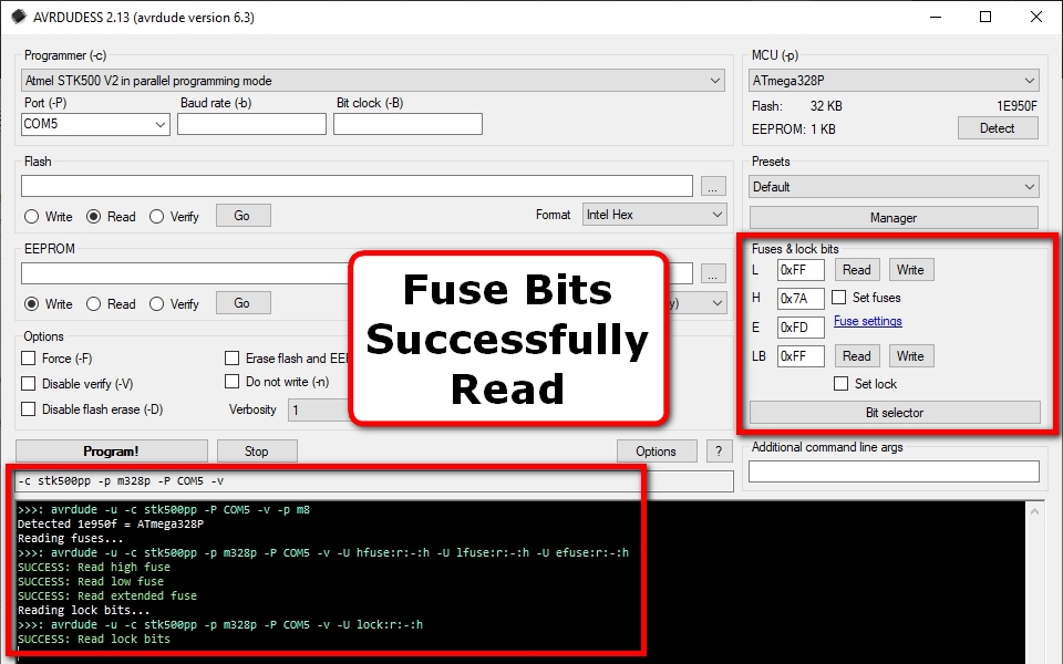
For example, in the above case, HVPP was used to detect and read the fuse bits of an otherwise unresponsive Pro Mini:
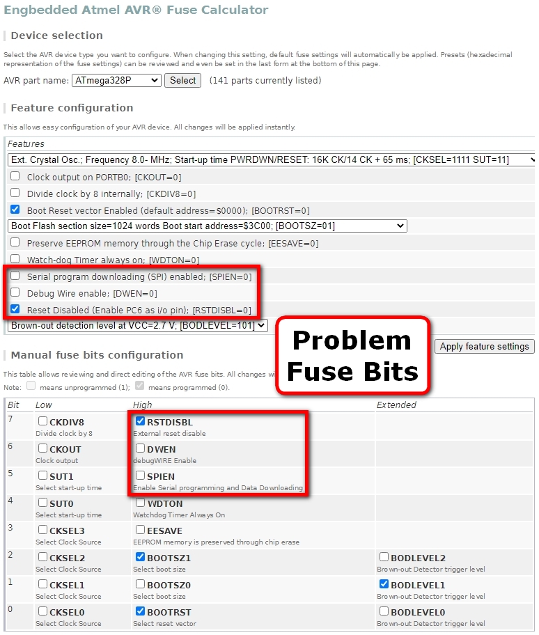
Click on the blue underlined “Fuse settings” link in the AVRDUDESS “Fuse & lock bits” panel to better understand the problem.
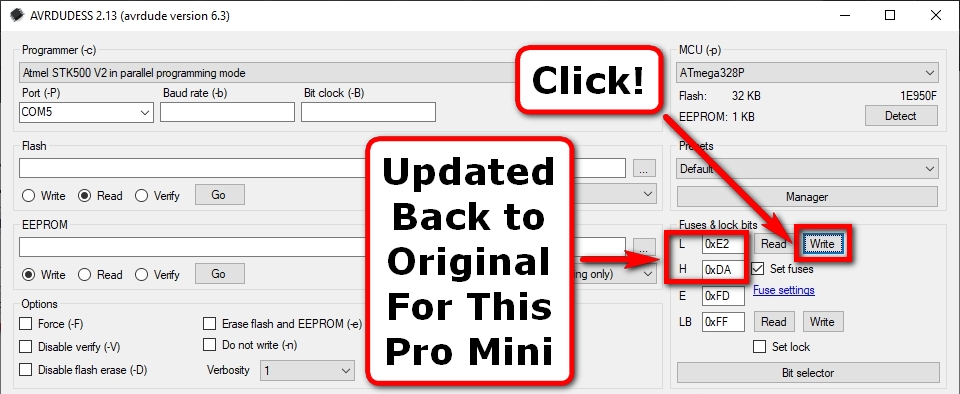
These problem fuse bits can now be corrected back to their original values – in this case:
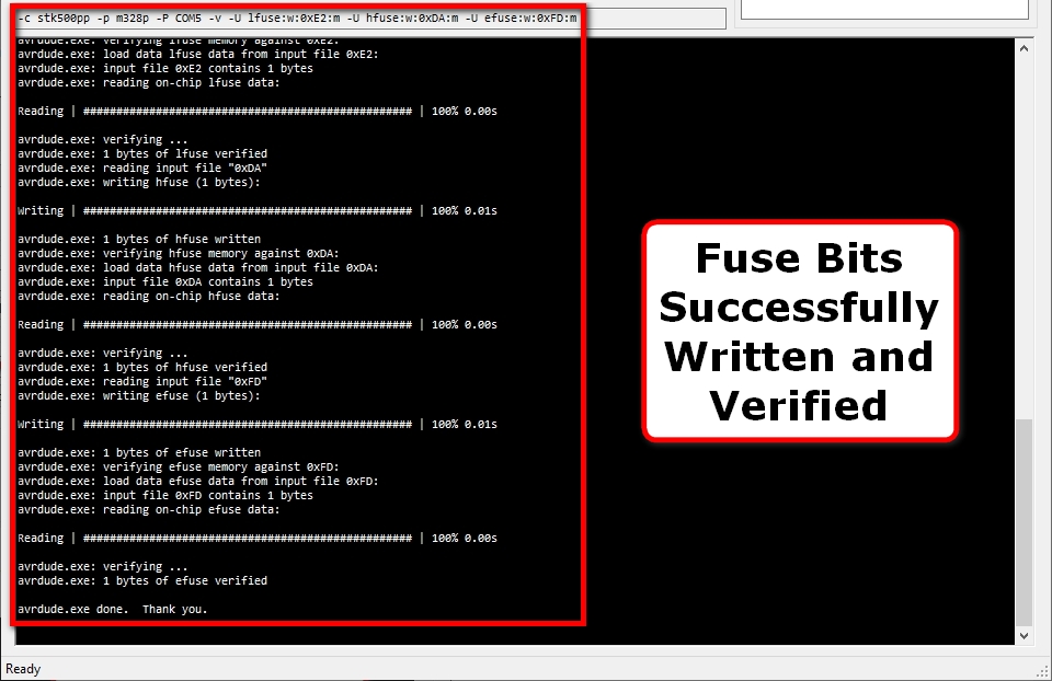
The AVRDUDE command and resulting messages are shown below:
Once corrected, the Pro Mini from above can then be detected and fuse bits read, etc. using standard ISP/ICSP as shown below:






Thank you for such detailed guide. I save my broken Arduino Pro mini 3V3 8MHz wiht your guide and code. I use BC327 PNP transistor as Mosfet and BC337 NPN transistor. As a proggrammer i use Arduino Nano for built in external USB connectivity and A7 pin. For the correct fuse setting I use boards.txt file located at Arduino IDE folder in program files. After the steps, I burn the bootloader to pro mini and it worked. I really enjoyed the journey and i am very greatful. Thank you, keep on rollin!