How to make an AVR Programmer out of a Pro Mini – Part 1: ISP/ICSP
Programming the Programmer
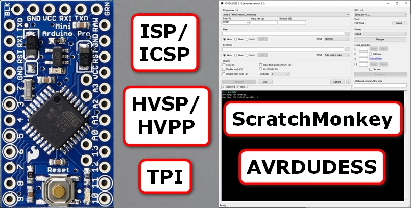
Following the steps below will use an existing 5v 16MHz Pro Mini to act as an ISP/ICSP/HVSP/HVPP/TDI programmer that understands (most of) the STK500v2 protocol.
It uses a slightly modified version of the excellent ScratchMonkey code by Matthias Neeracher – much thanks and appreciation should be directed his way!
This new programmer can then be used to change fuses, flash bootloaders and even potentially resurrect “bricked” AVR chips.
Part 1 of this series tests the ISP/ICSP functionality.
It also includes a useful feature that might enable the resurrection of a “bricked” Pro Mini whose CKSEL fuse bits have been incorrectly set.
Part 2 of this series details building some extra circuitry to test the HVSP/HVPP functionality.
This enables the programmer to resurrect a “bricked” Pro Mini whose RSTDISBL, DWEN and/or SPIEN fuse bits have been incorrectly set.
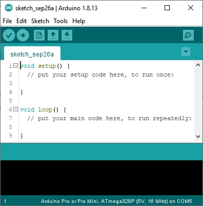
Step 1: Launch the Arduino IDE.
I’m using version 1.8.13 in the screenshots that follow.
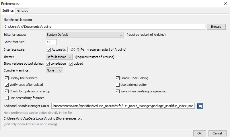
Step 2: Navigate to File ⇨ Preferences
Tip: Or just press Ctrl+Comma.
The following window should appear…
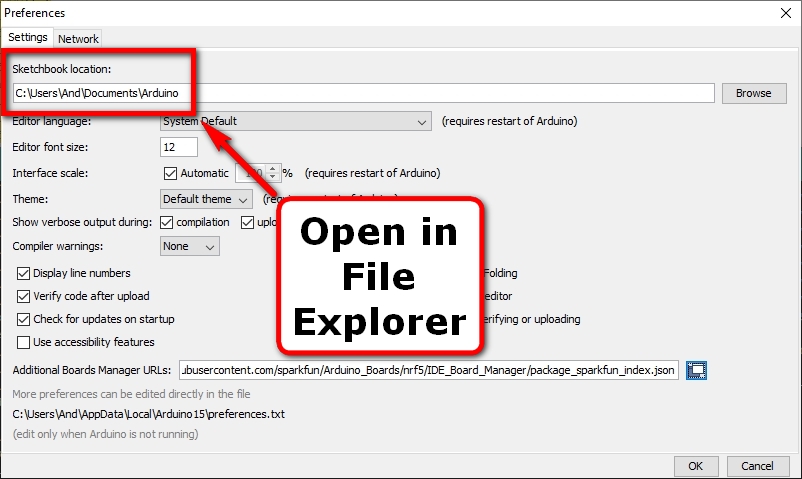
Step 3: Open the Sketchbook location in your favorite file explorer software.
Note: This location is where all your Arduino IDE sketches are normally saved to.
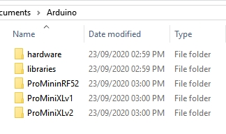
The contents of your Sketchbook folder should look something like the following:
Note: You will likely have many more folders (Sketches) than in the above screenshot.
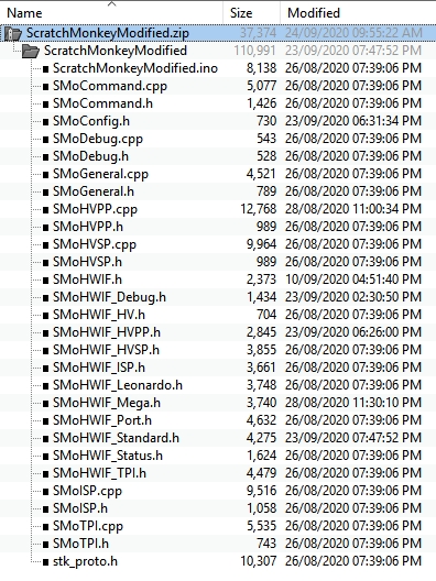
Step 4: Download and extract the ZIP archive from this Github repository into the above directory.
The ZIP archive contains the following files and internal structure:
Step 5: Close and relaunch the Arduino IDE.
Note: Adding new sketches to the Sketchbook directory from outside the Arduino IDE usually requires an IDE relaunch for those new sketches to get noticed.
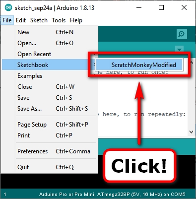
Step 6: Navigate to File ⇨ Sketchbook and select a sketch called ScratchMonkeyModified in the listing:
Note: You will likely have many more Sketches listed than in the above screenshot.
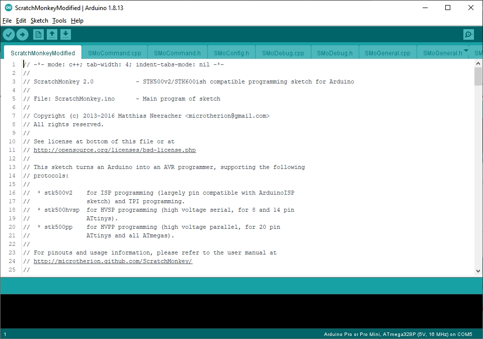
The Arduino IDE should update to display all the ScratchMonkey code in a series of tabs:
Step 7: Navigate to Tools ⇨ Board: ⇨ Arduino AVR Boards (Section) and select the following:
Ardunio Pro or Pro Mini
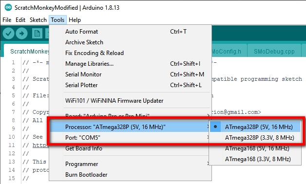
Step 8: Navigate to the Tools menu and select the following options for the Arduino Pro or Pro Mini board chosen:
Processor: "ATmega328P (5V, 16 MHz)"
Port:      "[Your COM Port Here!]"
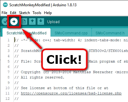
Step 9: Connect the Pro Mini that will become the Programmer to your existing FTDI programmer and upload the sketch.
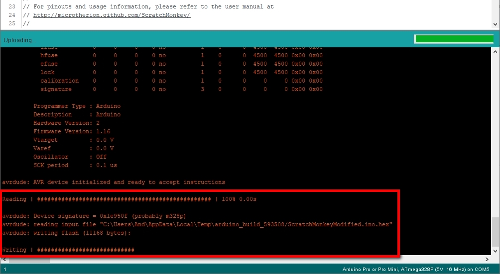
The Arduino IDE should now compile the Sketch code and, assuming there were no errors, will attempt to upload it using the FTDI programmer:
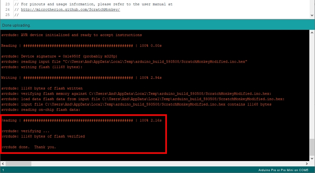
After uploading, the Arduino IDE will attempt to read back the compiled Sketch code written and verify that everything was written correctly:
Step 10: Verify that AVR Downloader/UploadDEr, a.k.a. AVRDUDE, can communicate correctly with the new programmer using the STK500v2 protocol.
Note: I’m using AVRDUDESS – a GUI for AVRDUDE – in the screenshots below. AVRDUDE can also be run on it’s own from the commandline.
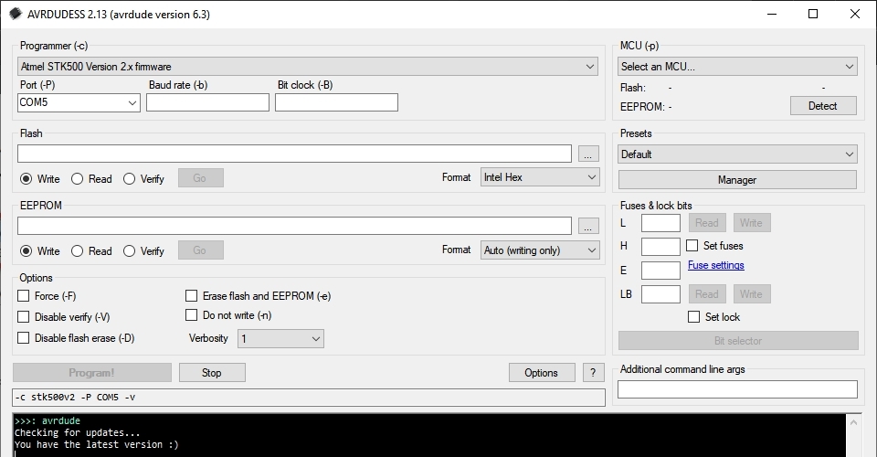
Select the following programmer protocol from the Programmer dropdown menu:
Atmel STK500 Version 2.x firmware
Select the COM port of the FTDI programmer attached to the new Pro Mini-based programmer from the Port dropdown menu:
Note: In the screenshot below, the FTDI programmer has been enumerated to COM5 – your programmer will likely be different.
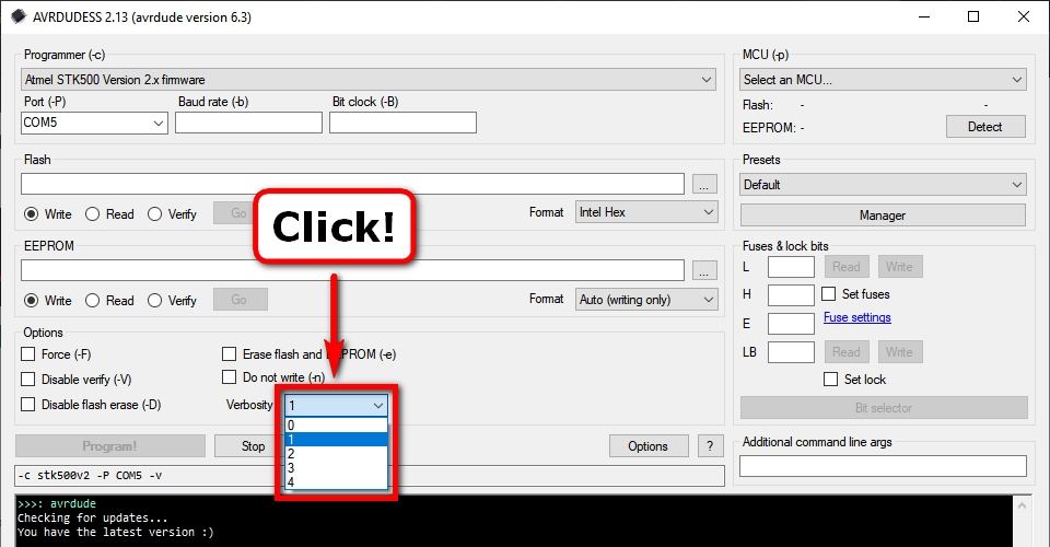
Select the a Verbosity level of 1 from the Verbosity dropdown menu:
Note: This will display the new (Pro Mini-based) programmer’s initial configuration message in the AVRDUDESS GUI – even with nothing attached to it.
Verify the AVRDUDE command used should look something like:
-c stk500v2 -P [Your COM Port Here] -v
Click the Detect button with nothing attached to the new Pro Mini-based programmer:
Note: Even though there is nothing attached to the programmer the increased verbosity will verify the new programmer is communicating correctly.
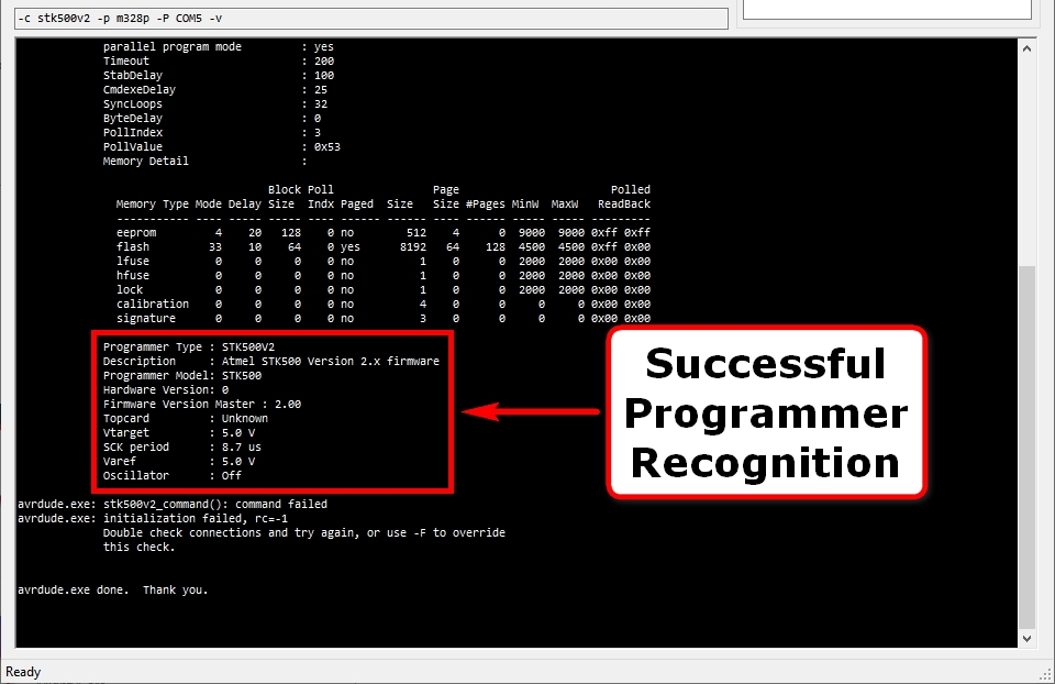
Assuming AVRDUDE successfully recognises a valid programmer on the COM port, something like the following message should be displayed:
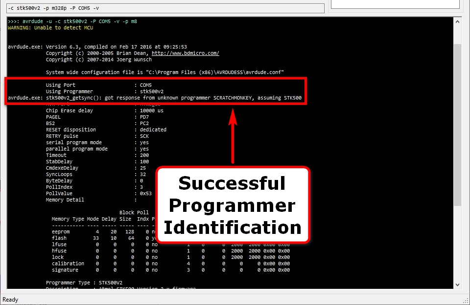
Scrolling further up the displayed messages should also reveal the correct, but currently unknown programmer identification:
You should now be able to connect the new Pro Mini-based programmer to the board you want to program.
Connecting the Programmer via ISP/ICSP
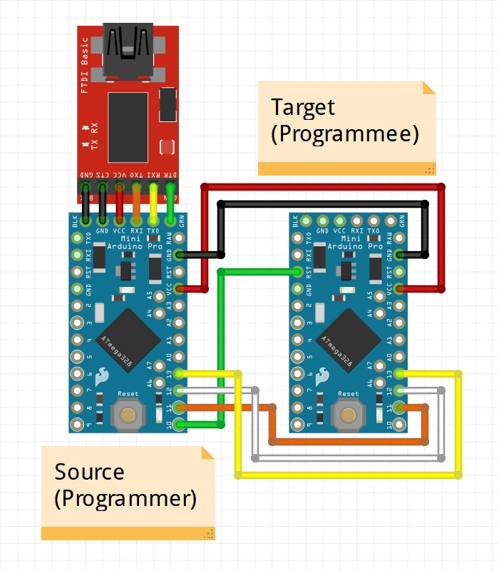
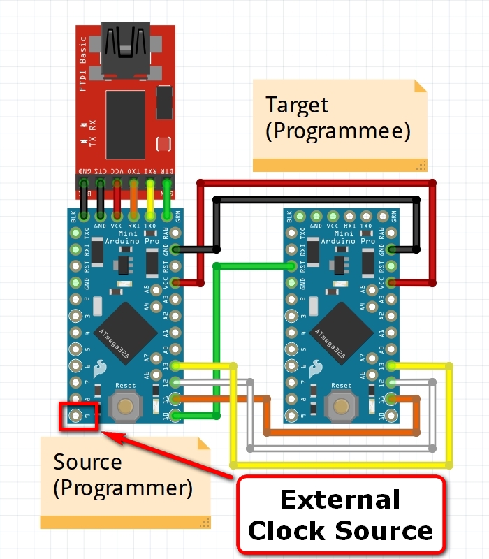
Step 1: Connect the new Pro Mini-based programmer to the target board you want to program using the following ISP/ICSP connections:
Step 2: Using AVRDUDE, attempt to detect the target microcontroller.
Note: The AVRDUDESS settings in the screenshots below remain the same as in Step 10 above.
Assuming detection is successful, the microcontroller type will be displayed:
Note: If detection is unsuccessful, first double-check the connections between the Pro Mini Programmer and the target board.
Note: If using AVRDUDESS, the GUI will update the detected Microcontroller type:
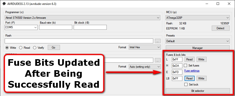
Once the target microcontroller has been successfully detected, its fuse bits can be read and, if necessary, modified:
Note: If using AVRDUDESS, the GUI will update the fuse bits read:
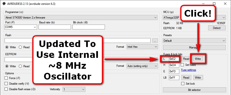
The microcontroller fuse bits can also be modified, for example, to use the internal ~8 MHz oscillator instead of an externally connected one.
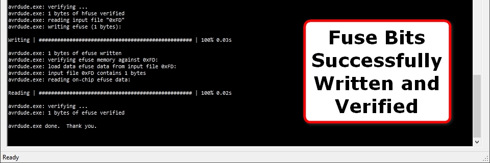
The fuse updating process will first write the fuse bits, then read them back and verify they have been correctly written:
The microcontroller’s bootloader can also be updated, for example, to increase the default upload UART speed and reduce upload error rate:
The flash writing process will first write the new bootloader to the microcontroller flash, then read it back and verify it has been correctly written:
Warning: Be careful updating the fuse bits since you may accidentally put the microcontroller into an unresponsive state. If this happens, read on!
Optional: Resurrecting an Unresponsive Pro Mini
Mistakes can be made when updating microcontroller fuse bits.
One common mistake is accidentally configuring the microcontroller to use an external oscillator when there isn’t one connected.
This can result in the microcontroller becoming unresponsive or responding with an unknown signature, e.g. 0x000102 as shown below:
The new Pro Mini-based programmer created above helpfully provides an external clock source (via PWM) on board pin 9 (PB1/OC1A) that may help in this case.
Note: If however, the SPIEN, DWEN and/or RSTDISBL fuse bits have been incorrectly set you will need to use the HVSP/HVPP feature detailed in Part 2.
Step 1: Connect the new Pro Mini-based programmer to the target board you want to program using the following ISP/ICSP connections:
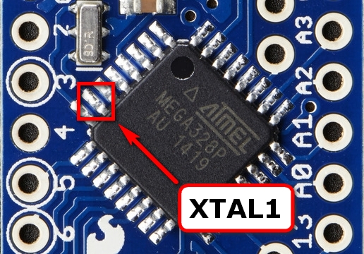
Connect a short wire from pin 9 on the programmer to the XTAL1 pin on your target board – for example, shown below on a ATmega328p chip.
Note: Try to make a secure/reliable connection, e.g. solder the wire – however you can sometimes get away with simply holding the wire to the microcontroller pin.
Step 2: Using AVRDUDE, attempt to detect the target microcontroller – the external clock source gets applied automatically.
Note: The AVRDUDESS settings in the screenshots below remain the same as in Step 10 above.
Assuming detection is successful, the microcontroller type will be displayed:
Note: If detection is unsuccessful, first double-check the connections between the Pro Mini Programmer and the target board – especially the XTAL1 pin.
It should now be possible to read and correct the fuse bits accordingly:
Once corrected, you should now be able to compile and upload code to your board without the external clock source applied.
Enjoy!
Note: If the target microcontroller is still unresponsive, you may need to use the HVSP/HVPP feature which will be detailed in Part 2.











Best guide on internet so far. (I have been looking such guide for2 straight days)